Connect the red probe to the anode and black probe to the cathode. After that you need to connect your multimeter probes to the Zener diode.

Set the knob of the digital multimeter in the voltage mode and place the terminals of the meter on the anode and cathode to test a diode.
How to test a diode with a digital multimeter. The multimeter then displays the voltage drop when the test leads are connected across a diode when forward-biased. The Diode Test procedure is conducted as follows. Make certain a all power to the circuit is OFF and b no voltage exists at the diode.
Voltage may be present in the circuit due to charged capacitors. If so the capacitors need to be discharged. Set the multimeter to measure ac or dc voltage as required.
Turn the dial rotary switch to Diode Test mode. It may share a space on. The digital Multimeter DMM has built in function for testing the diode.
On the functionality button there is marked a diode sign which indicates where to test the diode. We need to set the knob here. Once it is set there the internal circuitry of DMM has sufficient voltages for forwarding and reverse biasing the diode.
Ohmmeter Mode Testing Procedure Identify the terminals anode and cathode of the diode. Keep the digital multimeter DMM in resistance or ohmmeter mode by rotating the central knob or selector to the place. Connect the red probe to the anode and black probe to the cathode.
This means diode is. How to test LED Light Emitting Diode Disconnect the LED from the circuit and power supply if it is already connected in a circuit. Find the LED terminal ie.
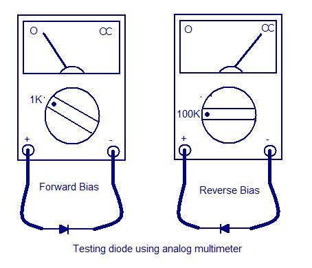
Anode and cathode as shown in above fig In case of digital multimeter set the meter on Diode Test Mode in case of analog multimeter. Step by Step Instructions. Identify the diode terminals anode and cathode.
Keep the digital multimeter DMM in diode checking mode by rotating the central knob to the place where the diode. Connect the red probe to the anode and black probe to the cathode. This means diode is forward-biased.
DMM Diode Test Position Many digital multimeters DMMs have a diode test function that provides a convenient way to test a diode. A typical DMM has a small diode symbol to mark the position of the function switch. When set to diode test the meter provides an internal voltage sufficient to forward-bias and reverse-bias a diode.
How to Test a Silicon Diode with a Multimeter Method 1of 3. Using the Diode Check Function. Check for a diode check mode.
Most digital multimeters have a diode check. Use this method when necessary. This method of testing diodes is less accurate.
Testing diode with digital multimeter Nowadays the digital multimeter has a diode testing option where you test the diode. First of all move the knob to the small diode symbol for testing a diode. Then connected the diode anode to the red lead of meter and cathode to the black lead to make it forward bias.
Testing of Zener Diode with a multimeter The first step is to Identify Zener diode anode and the cathode. After identifying the anode and cathode of the Zener diode Place your multimeters knob to voltage mode. After that you need to connect your multimeter probes to the Zener diode.
Testing diodes with a multimeter. How to test a diode with a multimeter The basic diode test is very simple to perform. Just two tests are needed with the multimeter to ensure that the diode works satisfactorily.
The diode test relies on the fact that the diode will only conduct in one direction and not the other. The diode test feature is usually combined with continuity test and is represented by a Diode Symbol. To test a diode set the knob to Diode Test mode and connect the Red probe to Anode of the diode and Black probe to Cathode of the diode.
If the diode is working properly the Multimeter will display the forward voltage drop across the diode. A Short Easy Test To Check If A Bridge Rectifiers Shorted or NotHope This Helps Someone Out There. Shut off the device and set your multimeter to the ohm setting.
Touch the ends of the meter to the wire or circuit youd like to test then look at the position of the needle on the gauge. It should read 00 or show a very low reading if continuity is present. Procedure to Test a Diode As in the case of a p-n junction diode firstly ensure the cathode and anode terminals of the diode.
The circuit should be as per the diagram shown. Set the knob of the digital multimeter in the voltage mode and place the terminals of the meter on the anode and cathode to test a diode.