Use the wire strippers and remove ¾ of an inch of the wires insulation to reveal bare copper. Solder its free end to a volume pot chassis.

This is a Double Pole Double Throw DPDT momentary illuminated momentary rocker switch It has one ind lamp at the top.
How to wire a dpdt switch. Remove all electrical power from the power source. Use the wire strippers and remove ¾ of an inch of the wires insulation to reveal bare copper. Do this on all wires that are being connected to the DPDT switch.
Connect the positive power wire from the power supply to one of the center screw terminals. Tighten the screw with a screwdriver. A Double Pole Double Throw toggle switch is a combination of two individual SPDT Single Pole Double Throw switches connected in the single assembly.
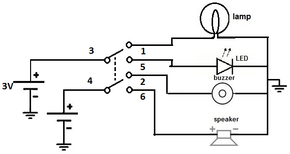
Look at the figure 12 the centre dotted line indicates that the DPDT switch is actually two SPDT switches in one package. They are mechanically coupled to control different circuits at the same. Wire a DPDT Rocker Switch for Reversing Polarity Step 1.
Connecting the Wires to the Disconnect Terminals. First you need to cut a bit off each wire that will be going. Connecting the Wires to the Disconnect Terminals for Power.
Similar to the last. Below is the schematic diagram of the wiring for connecting a DPDT toggle switch. A DPDT toggle switch has 6 terminals.
Terminals 3 and 4 represent the toggle switch. These terminals receive the power necessary to drive the loads on terminals 1 and 5 and 2 and 6. Terminals 3 can flip between terminals 1 and 5.
DPDT switch is nothing bit double pole double throw if you want 2 thing at a time to switch on then you can use dpdt switch it comes in different types. You can use as per your wish to switch on things at a time. With simple wiring a toggle rocker or pushbutton DPDT ON-ON switch type can be used to create a 4-Way switch.
DPDT_4WAY 30331537 186 KB Example SPDT On-On type Switches that could be used as 3-Way Switch. How to Connect a DPDT Relay in a Circuit. In this article we go over how to connect a Double Pole Double Throw DPDT relay in a circuit.
In order to know how to connect a DPDT relay you must know what each pin terminal represents and how the relay works. A Double Pole Double Throw Relay comes with 8 terminal points. As long as power is connected to the switch one is always On.
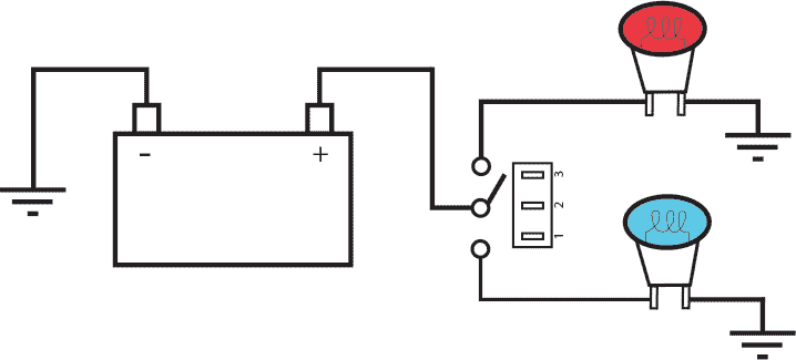
In the below example the red light is illuminated in one position and the blue light is illuminated in the other position. DPDT Toggle Switch Dual Position Dual Throw A DPDT switch can be a bit confusing. It might be easiest to consider it to be two SPDT switches.
Wiring is dead simple. The pads labels match up to every Aion PCB project so you can run the wires straight across and be done with it. 3PDT Stomp Switch Instructions Refer to diagram 3 to wire a single color LED and diagram 4 for a 2-color 3-lead LED.
This is a Double Pole Double Throw DPDT momentary illuminated momentary rocker switch It has one ind lamp at the top. The wiring diagram to the right will show how to wire and power this 12V 20AMP ON-OFF-ON 3 way Carling Contura rocker switch. The wiring diagram to the right shows how the.
Some clarity on the wiring of a Contura V momentary on-off-on DPDT switch. If you have a 4-wire winch controller you connect the two out wires to 2 and 1 and Or get the right diagram and Ill confirm your thoughts. Using a toggle switch to actuate an electrical application is very common.
Hook up anywhere from 1 to 4 different accessories depending on the configuration of your switch. Here we will wire a SPST and a DPDT toggle switch. What Youll Need Toggle Switch Electrical Wire Wire Terminals Crimp Tool Step 1 Start by crimping your wire.
Solder an output wire from the combined middle terminal on the toggle switch and run the wire through the guitar to the output jack soldering it to the terminal on the jack. Solder a wire to the grounding terminal running it through the body of the guitar to the wiring cavity. Solder its free end to a volume pot chassis.
Connect a wire from 3 to 4 and another wire from 1 to 6. These wires will form an X across the center of the switch. Only one of these wires needs to be insulated as long as both are too tight or too rigid to move and touch other pins.
The 3 is used by the ground for the switch lights and the 6 is used by the blue switch light wire. All very confusing especially with the two lights in the switch in the circuit but I have discovered that my GLS II 15 ftrs nav lights are wired to a dpdt switch just like this one from what I can tellWiring Common Switching ApplicationsHow. Connect the black wire negative power to the DPDT switch as shown above.
Youll need one long piece of wire coming from the battery to the lower switch terminal. And youll need a smaller piece of wire coming from the lower switch terminal to the opposite terminal as shown. Solder the yellow and blue motor wires to the DPDT switch.