Wiring diagram discussion in the Farmall International Harvester IHC forum at Voltage Regulator. Always do this step.

The magnetic field produced by the current attracts a moving ferrous core held back under spring tension or gravitational pull.
How to wire a voltage regulator. Remember the input voltage has to be larger than the voltage that the regulator regulates out. In this case we are using a LM7805 which outputs 5 volts. In order for the regulator to output 5 volts the voltage entering has to be at least 2 volts higher so it has to be at least 7 volts.
7 volts would work perfect. Cut a length of solid core wire long enough to join one of the unconnected potentiometer wires to the remaining wires of both the capacitors. Connect the remaining potentiometer wire to the one you just soldered the solid wire to.
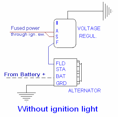
Connect the wire to the terminal marked B sometimes this terminal is marked BATT. Connect the generator or alternator wire to the regulator. The corresponding terminal for the generatoralternator wire is marked an A or G sometimes ARM or GEN.
Connect the field wire – field coil wire – to the field terminal on the regulator. Looking for CAR REPAIR MANUALS. Click the LINK belowhttpbitly2mtp7QJWANT TO BUY TUNING INSTRUMENTSBelow are the links of tuning instrument i used on my.
How to Wire an Alternator Voltage Regulator Step 1. Open the hood of your car. Ensure the engine is cool before wiring the alternator voltage regulator.
Remove the black battery cable from the cars battery terminal using a wrench. Remove the red battery cable. Locate the voltage.
Connect wire F of your regulator to the generators field wire connect A is to the generators armature and attach BATT to the positive terminal of the battery. BATT is usually brownyellow F is yellowgreen and A is mostly brown bear in mind that these colors are subject to change according to the make of the device. Wiring diagram discussion in the Farmall International Harvester IHC forum at Voltage Regulator.
GEN light blue to generator A. How to convert a tractor from 6 volt to a 12 volt system - 62310 Feel free to donate with crypto below if you found this video helpful. GM Externally Regulated Alternator to Voltage Regulator Wiring.
Wiring instructions for the early GM Delco Remy external regulated alternator. How to wire an external voltage regulator on a GM vehicle. The early GM alternator is the 10DN series alternator and was used on GM vehicles from about 1963-1970.
In electromechanical regulators voltage regulation is easily accomplished by coiling the sensing wire to make an electromagnet. The magnetic field produced by the current attracts a moving ferrous core held back under spring tension or gravitational pull. Attach the red wire to the input pin and the black wire to the ground pin.
Doing this will give you the input voltage reading. This voltage reading should typically be around 1-2 volts higher than what the regulator is designed to output. Harley davidson voltage regulator wiring diagram see more about harley davidson voltage regulator wiring diagram harley davidson voltage regulator wiring diagram.
1970 xlch 132 bobber new. Oem harley davidson stock 74540 01 voltage regulator 38 amp wiring 01 06. We remove the old regulator and the wire off the 30 amp breaker.
The original field wire that ran to the FLD plug on the original voltage regulator green wire needs to be connected with the wire that ran to the IGN side of the original voltage regulator. This wire both the old FLD and the old IGN need to be connected to the center plug on the newer voltage regulator as well. One more important step is required the new voltage regulator must have a good case ground - to its mounting surface.
If there isnt a good ground to the new voltage. Step 1 Disconnect the battery. Always do this step.
Step 2 Locate the voltage regulator usually on the firewall. Remove the ARM and FLD wires and tape them back with electrical tape in case you or the next guy want to re- install a generator. Used the Files section to install the Transpo Voltage Regulator after deeming Man that is quite a lot of work and requires running the wiring.
A voltage regulator generates a fixed output voltage of a preset magnitude that remains constant regardless of changes to its input voltage or load conditions. There are two types of voltage regulators. Linear and switchingA linear regulator employs an active BJT or MOSFET pass device series or shunt controlled by a high gain differential ampl.
The voltage regulator field. May 03 Simple visual explanation of the wiring of the 6 volt Generator Regulator on My Farmall Super A 6 Volt Positive Ground. May apply to others.
Jun 20 wiring diagram discussion in the Farmall International Harvester IHC forum at Yesterdays Tractors.