Alternator ground connection is the casing grounding back through bracketing and eventually through battery ground cable. Start the alternator swap-out by disconnecting both battery cables from the battery.
Then loosen the locknut to the BAT cable and remove the ring terminal.
How to wire alternator. Step 7 Figure 1 Take the long red 10 gauge wire and connect to the back of the alternator 1032 stud. This is the same place the red wire from the DA plug connects. Take the other end of the long red wire and connect directly to one terminal of the ammeter cut to size and install small ring connector.
Wiring harness and simplifies installation by using only one wire for charging. R Simply connect one wire from the positive battery terminal to the positive alternator terminal. 1 Left terminal NO CHARGE WARNING LIGHT Note that our 1-wire alternators 7127 7139 and 7140 permits the use of a no charge warningdashboard indicator light.
To wire a warning light remove the terminal plug cover. This video shows you how to wire a Single Wire Alternator on TractorsWe are showing this example on an MF 35 Deluxe Tractor but the same wiring will work on. Buy Here One Wire Alternator Wiring Diagram.
One wire alternator wiring diagram You will need an extensive professional and easy to comprehend Wiring Diagram. With this kind of an illustrative guidebook youll have the ability to troubleshoot stop and total your projects easily. 12 Volt Wiring Diagram Ford 8N Tractor 1 Wire Alternator Wiring 12 Volt Alternator Wiring Diagram.
You are able to usually count on Wiring Diagram as an crucial reference that may assist you to conserve money and time. Using the assist of the book you are able to effortlessly do your personal wiring assignments. But what sets the Tuff Stuff alternator apart from others is the fact it can be used as a one-wire or a factory-designed three-wire system.
Using the alternator in either instance requires no extra effort on the part of the end user. If you want to use it as a one wire connect the charge wire to the battery and alternator and youre done. One of these is the sense terminal.
You connect the output of the alternator back to this terminal so that it can sense and regulate the output voltage. The other terminal is the exciter. This is what excites the field of the alternator.
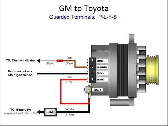
The following diagram shows the wiring for a typical 3-wire alternator connected to our Infinitybox system. The three wire types in a three-wire alternator include the battery positive wire the voltage sensing wire and the ignition input wire. The battery positive wire connects to the starter.
The voltage sensing wire connects to the battery and the ignition wire connects from the alternator to the key switch. The only thing required to electronically hookup a one wire alternator is to run a charge wire from the battery terminal on the alternator to the positive terminal on the battery or any positive battery source. The external regulator can be either totally removed from the firewall or left in place.
Connect the power cable and monitor harness. Reconnect the wire harness and insert the bolt that secures the main power cable to the alternator in the same order you removed them. They should install exactly as they were in the old alternator.
Make sure the primary power cable is tightened firmly onto the new alternator. Alternator ground connection is the casing grounding back through bracketing and eventually through battery ground cable. Make sure all connections including battery ground cable are clean and tight.
This is a basic wiring guide and will not cover every application or scenario. Always use caution when modifying a system. The 10- and 12-SI units use a different two-wire connector plug on the rear of the alternator.
The Number 1 wire on the 10- or 12-SI is connected to the charge warning light on the dash. The Number 2 wire is what is called the voltage sensing wire. Collection of denso alternator wiring schematic.
A wiring diagram is a simplified traditional pictorial depiction of an electrical circuit. It reveals the elements of the circuit as simplified forms and the power and also signal connections in between the tools. Follow the battery positive cable from the battery to where it is connected on the starter relay.
Install a 10-gauge wire to this terminal with a ring connector and run the wire to the back of the alternator. Connect this wire to the the insulated stud output terminal on the back of the alternator with another ring connector. The only thing you need to hook up on a one-wire alternator is a charge wire from the terminal on the alternator to the positive terminal on the battery or any positive battery source.
The external regulator can either be totally dismantled from the firewall or left in place. If left in place be sure to disconnect the wiring harness from the regulator. How does a 3 wire alternator work.
Disconnect the battery negative terminal. Connect a length of 10 gauge wire to the output stud on the back of the alternator using a solderless ring connector. Plug the alternator connector in the receptacle on the alternator.
Splice a 10 gauge wire to the larger. Depress the latch clip on the electrical connector going to the voltage regulator and wiggle it out. Then loosen the locknut to the BAT cable and remove the ring terminal.
Start the alternator swap-out by disconnecting both battery cables from the battery. Then remove the wires and cables from the back of the alternator Photo 2.
